
As traffic safety, congestion and other issues are widely concerned, a vehicle terminal system based on OBD and GPS is designed. The system is designed from two aspects, one is
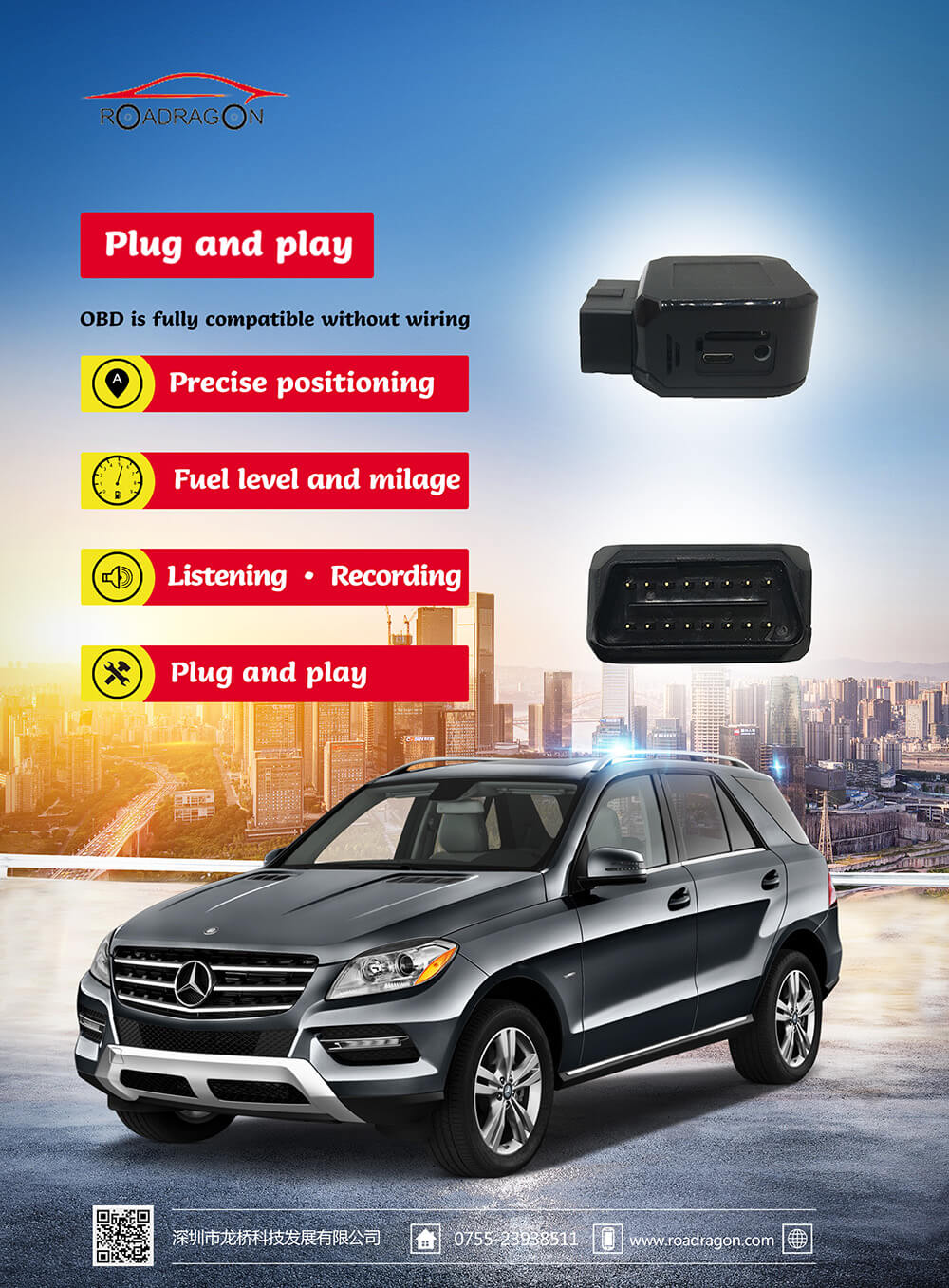
Based on the OBD interface to collect real-time data of the vehicle during driving, the acquisition circuit is designed to connect with the OBD system of the car by using the EST527-minis car networking OBD module to read the real-time operating parameters of the car while driving, so that the car owner can pass this system More intuitively understand the real-time parameters of the vehicle, and have a more comprehensive understanding of the vehicle condition, thereby reducing potential safety hazards. The second is to realize the accurate positioning of the vehicle through the GPS module on the basis of obtaining the information of the vehicle, and use the DSRC technology to realize the real-time interaction of various information between the vehicles to ensure that the vehicle is in a safe driving state. By mounting the system on a real vehicle, testing the functions of each part of the entire terminal device, the expected goal was achieved.
Due to the rapid growth of car ownership, a series of traffic problems caused by this have attracted more and more attention, such as safety, environmental protection, and road congestion.
Wait. From the perspective of driving safety, it is very important to maintain a distance between vehicles and drive carefully. Knowing the distance between vehicles can effectively solve such problems. In measuring the distance between vehicles, ultrasonic distance measurement technology is a commonly used distance measurement method, but its distance measurement environment conditions are relatively high and the accuracy is insufficient. Lidar is currently an advanced dynamic ranging method. It is mostly used in high-end scientific research experiments and tests such as unmanned vehicles. It is expensive. Civil Lidar is mostly used for reversing distance measurement within 3m. These two types of distance maintenance systems require high operating environment and high cost, and cannot meet the requirements of the safety distance reminding system for ordinary civilian vehicles.
At present, the vehicle-mounted GPS navigation system is widely used due to the advantages of high positioning accuracy, low cost, and convenient use. Measuring the distance between vehicles through GPS has become
For reality. The DSRC Internet of Vehicles communication technology has been continuously applied in the field of intelligent transportation in recent years, and it can be effectively established between high-speed vehicles.
At the same time, drivers are also eager to know some data during the driving process of their car, so as to realize more proactive management of the vehicle. The promotion of OBD-II technology makes it easier for people to obtain these data. The continuous development of the Internet of Vehicles technology provides a platform for the integration of various modules.
This system makes full use of the multi-mode fusion characteristics of the Internet of Vehicles platform, and designs a vehicle terminal system based on OBD and GPS. The system uses the comprehensive and fast characteristics of OBD to collect vehicle data, GPS technology positioning and ranging functions, and DSRC technology transmission The real-time nature of the data collects vehicle information and surrounding road information, filters, calculates, and distributes it through the processor to realize the information interaction between vehicles and roads. This article uses data splicing technology to effectively solve the fragmentation problem in the process of data collection and distribution, to ensure the correctness of data transmission, and to avoid the disadvantages of expensive distance measuring devices and high requirements for distance measuring conditions in the prior art, making vehicles in complex situations Accurate data information can still be obtained by downloading, which greatly improves the driving safety of the vehicle, and realizes that the various data of the car when the car is driving can be presented to the user in a simple and intuitive manner, which is convenient for the user to use.
1 System overall scheme design
After a comprehensive demand analysis of the system, the overall framework of the system is designed, as shown in Figure 1. The system is divided into three parts: software and hardware, the first
Part of it is to design a collection module for the on-board OBD system of a car, through which the real-time information during the driving process of the vehicle is extracted; the second part is a module that uses the GPS data to achieve information interaction through the DSRC; the third part is based on the collected data The data is visually designed, including LEDs and mobile devices, so that users can make corresponding adjustments to the driving state of the vehicle.
1. 1 System overall structure
This system is based on the design of the on-board OBD and GPS on-board terminal system. The vehicle-mounted system obtains the real-time driving data of the vehicle and the status information of some of the vehicle modules, as well as the data information of the GPS positioning module, and shares data with other vehicles through the DSRC vehicle networking communication module. root
Calculate the safe distance between the two vehicles based on the vehicle speed and the target vehicle speed. At the same time, calculate the actual distance between the two vehicles through GPS information, display the obtained distance information on the LED screen, and judge whether the actual distance is If it is less than the safety distance, the driver will be warned. The Bluetooth communication module is used as the information transmission medium between the vehicle terminal and the mobile device, and the divided circuits and functional modules are designed.
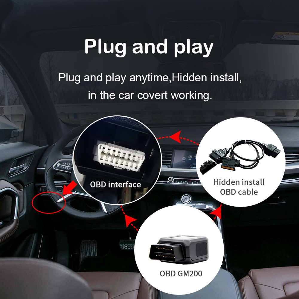
1.2 Design scheme of OBD data acquisition part
The OBD system was originally born to limit the emission of car exhaust. With the development of technology, the most widely used vehicle
The diagnosis system is OBD-Ⅱ, and the most advanced OBD-Ⅲ has been able to enter the system ECU (computer) to read the fault code and related data, and use the small on-board communication system to convert the vehicle’s identity code, fault code and location Such information is automatically notified to the management department. Considering the current diagnostic interface chips on the market and comparing with other chips, we finally chose Est527_minis as the core of the hardware circuit design. At the same time, EST527 covers all mainstream automobile agreements and has strong applicability. Most models on the market can be used. The collected information is displayed on the LED display. Here, the HC-06 Bluetooth module is used as the transmission medium with the mobile device, and the communication distance is about 10m.
![]() 1.3 Part of the design plan for the measurement of the driving distance
1.3 Part of the design plan for the measurement of the driving distance
As shown in Figure 4, this part obtains GPS positioning information of the vehicle through the GPS positioning module [14], and obtains other information with the help of the DSRC vehicle networking communication module.
The vehicle positioning information is calculated and the distance between the two vehicles is displayed on the LED display or mobile device. When the distance is less than the set safe distance, the sound and light alarm module will alert the driver. The ARM core controller in the system uses the STM32F105RBT6 chip, the DSRC vehicle networking communication module uses the MK5OBU-DSRC component, the GPS positioning module uses the MK5OBU-GPS component, the LED display uses the car 14 inch display, and the sound and light alarm module uses audio playback.
1.4 Software part design
This part develops the mobile device AP[15] for the Android platform, focusing on the division of module functions, forming a clear software framework
The software design module is mainly divided into 5 parts: the dashboard display module for car speed information, the list display module for overall vehicle information, the map service module, and the Bluetooth module for receiving information and the sliding module for displaying basic information. After integrating each part of the module design, the final vehicle terminal system is designed
2.1 Test environment
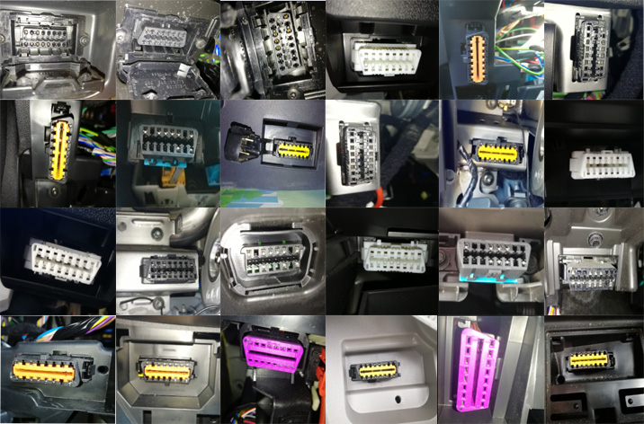
The basic test environment of the system is shown in Table 1, and then the preparation work before testing the corresponding modules: install the on-board terminal on the two vehicles and
Connect with the OBD-Ⅱ interface, check the power supply of each module, and at the same time transfer the information of the smart phone to the vehicle terminal via Bluetooth on a straight road about 1km long, and the two vehicles will start in turn to check the working conditions of each module of the system during driving. Perform tests to verify the stability, practicability and accuracy of the system.
2.2 Test results
This system selects a real vehicle to test the system. The test results show that the vehicle-mounted terminal can integrate various modules and smoothly realize the expected design functions.
1) In terms of data collection, both vehicles can accurately view the real-time information of vehicle driving on the LED display and mobile devices, which is intuitive and convenient as shown in the figure
7 shown.
2) In terms of driving distance measurement, in order to verify the accuracy of the measured distance, when the vehicle starts and stops, the distance between the two vehicles is measured with a meter stick.
So as to compare with the data measured by GPS. It is mainly divided into two groups of experiments: 1) The vehicle in front is stationary, and the vehicle behind starts to approach the vehicle in front within 100m and stops after reaching a certain distance; 2) The two vehicles start at about the same time and stop after driving for a period of time.
During the two sets of experimental tests, the system used the GPS ranging module to separately record the relationship between the distance between the two vehicles and the time. After multiple measurements and average values, it was found that the error between the GPS ranging and the actual distance was within 0.5 m. When the vehicle distance is less than 2m, the error will increase. It shows that this system can basically obtain the distance information between vehicles accurately and quickly by using the GPS positioning system, and can interact with the position information between the two vehicles in real time through DSRC, so as to remind the relative position of the vehicles.
3 Conclusion
Roadragon has designed an on-vehicle terminal system for the Internet of Vehicles based on OBD and GPS. The terminal system mainly includes two parts. The first part is the vehicle real-time data acquisition module, and the second part is the calculation and warning of the safety distance between vehicles through DSRC and GPS. Features. The actual vehicle test results show that the various modules of the vehicle terminal system work normally, are reliable and practical, and can be used by most models on the market. While ensuring safe driving, the driver can also obtain real-time driving information of the vehicle and part of the information of the vehicle that is also equipped with the device, so that the owner can have a more comprehensive understanding of the car’s situation and travel more comfortably. Because the system is connected to the Internet of Vehicles platform, when the number of vehicles is large, it has high application value in vehicle driving behavior analysis, fleet management, and environmentally friendly driving based on vehicle big data.
Post time: Sep-18-2020